[DigiKey TechForum] Guide to Implementing Negative Voltage Rails for System Power Design 2: Negative Voltage Requirements for Communication Interface Noise Suppression and Precision Measurement
TECHWORLD · · 1 views
✦ AI Summary
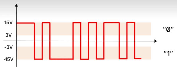
The RS232 standard distinguishes logic 1 and 0 with positive and negative voltages, with logic 1 corresponding to -12V and logic 0 to +12V.
Negative voltage is used to improve immunity to external interference in long-distance cable transmission and to reduce common-mode noise, and it may be required in industrial serial communications.
This article explains that the noise, ripple, and voltage stability of the -2.5V negative voltage rail are important in circuits for measuring weak photoelectric signals.
In some digital and communications circuit interfaces, logic 1 and 0 are distinguished by positive and negative voltages. The RS232 standard is one such example.
In this case, the voltage corresponding to logic 1 is -12V. The voltage corresponding to logic 0 is +12V.
Negative voltage is used to improve immunity to external interference during long-distance cable transmission. It also helps reduce common-mode noise.
These voltage conditions need to be met in industrial serial communications. In industrial environments, such conditions are treated as one of the prerequisites for communication.
Without negative voltage, communication errors may occur. The likelihood of packet loss also increases without negative voltage.
This approach is used in the serial communication ports of industrial PLCs and in RS232 ports for equipment debugging. It is also used in data communication between differential communication modules and industrial control devices.
To implement standard signal levels, a voltage rail of ±10~±12V is required. As the magnitude of the negative voltage increases, error immunity improves in long-distance signal transmission.
By using the on-chip charge pump, negative voltage can be generated from a single 5V power rail. This makes it possible to supplement sufficient negative-voltage configuration under single-supply conditions.
If only a single positive supply is provided to a high-speed operational amplifier, the output voltage cannot fall below 0V. As a result of this single positive-supply operation, the negative portion of an AC signal is clipped.
When the negative portion is clipped, it is difficult to fully restore the original signal. Therefore, when handling AC signals, preserving the negative portion is important.
Examples of fields that require precise signal acquisition include photoelectric detection and the measurement of weak signals from high-impedance sensors. In these fields, linear amplification of the entire AC waveform is required.
A dual-supply architecture with a separate negative voltage rail is essential as the power structure for linear amplification of the entire waveform. A typical negative voltage rail level is -2.5V.
The LTC6268 is a wideband precision operational amplifier for fA-level low-current sensing circuits. With the LTC6268, the requirements for noise, ripple, and voltage stability on the negative voltage rail are extremely stringent.
The quality of the negative voltage supply determines the accuracy of the device's signal acquisition. In particular, the -2.5V negative voltage rail is the focus of this article. If voltage distortion or excessive noise occurs on this negative voltage rail, weak photoelectric signals may be buried in noise. As a result, the entire set of measurement data may be rendered invalid.
In the circuit configuration, the operational amplifier's positive (+) supply is set to +2.5V. The noninverting input (+) of the operational amplifier is directly connected to system ground (0V). The operational amplifier's negative (-) supply is provided at -2.5V.
The anode of the photodiode is connected to +2.5V. The cathode of the photodiode is connected to the inverting input of the operational amplifier. With this connection, the photodiode is reverse-biased.
Applying reverse bias to the photodiode greatly reduces the junction capacitance. As the junction capacitance decreases, the circuit bandwidth expands.
When light is incident, a photocurrent (IPD) is generated in the photodiode. This photocurrent (IPD) flows from the cathode to the inverting input terminal of the operational amplifier. The photocurrent (IPD) is the input signal of the circuit.
The magnitude of the photocurrent (IPD) is at the pA to nA level. The photocurrent (IPD) is a very small signal. Therefore, if voltage distortion or excessive noise occurs on the -2.5V negative voltage rail, this weak photoelectric signal may be buried in noise, and as a result the entire set of measurement data may be rendered invalid.
The suitable device for this circuit is the LTC6268 high-speed precision operational amplifier. The LTC6268 has a FET input stage and fA-level input bias current characteristics, minimizing loss of weak photocurrent and making it suitable for detecting weak photoelectric signals with ultra-low-noise input current characteristics. In addition, the LTC6268 has a closed-loop bandwidth of 65MHz in a 20kΩ feedback resistor configuration.
In this circuit, the 20kΩ feedback resistor is the core element of transimpedance conversion, linearly converting photocurrent (IPD) into an output voltage with a 20kΩ transimpedance gain. However, parasitic feedback capacitance arises from the resistor terminals, PCB traces, and the photodiode junction, and it behaves as an equivalent element in parallel with the feedback resistor. This parasitic capacitance and the 20kΩ feedback resistor form an RC low-pass filter, reducing bandwidth and also creating the possibility of high-frequency oscillation.
Accordingly, the operating conditions require a -2.5V negative voltage rail, which is intended to enable negative swings in the output voltage. In actual circuit design, a compensation capacitor is added as a countermeasure to reduce the influence of parasitic components.
DigiKey's TechForum/Article was provided as the path to the original source.
The provided text does not contain the body of the article, but only indicates where to view the original text, so the only extractable fact is the reference path.
Source: TECHWORLD · Lee Gwang-jae
Original: https://www.epnc.co.kr/news/articleView.html?idxno=408291
References
This article was produced with the help of an automated content generation algorithm.
Source: TECHWORLD
View originalThis article was summarized and organized by BizCrush based on the original article from TECHWORLD. For exact quotations and full details, please refer to the original article.